
How to model data (pt. 3) – applications and physical data models
In the previous articles of this series, we looked at the major questions that will be answered when data modeling, and had a look at how to create conceptual and logical data models (part 1). We then looked at how logical data will be used in other models, such as processes or application landscapes. We also had a deeper look at how to model data exchanges at technical interfaces (part 2).
In this article we will have a look at the physical data models. We will answer questions like “which tables are in this application” and “what are the fields in the tables and how are they defined”. The series will close out with the question “where do I ask for the data” and focus around screen models in solution designs in the next article.
Applications and data
Last week we looked at how data is used in describing data exchanges at technical interfaces and how it might be mapped/transformed (see graphic below). The question now is how data will be stored in the applications.

The first thing to answer this question is to determine if your application has a built-in storage (database) or if it relies on an external database system to hold the data. This opens the question if we are talking about a logical application model or a physical application model (using “application instance” objects rather than “application system type” objects).
Either way, it is a good idea to have two additional models in your repository for each application system type:
- A profile of the application (which technology does it run on, who is responsible, who is using it, what additional documentation, and
- The mapping of the logical application (type) to its instances, which then can be used in physical diagrams, such as network diagrams.

On the right hand side in the graphic above, you can see that the PRO-ORDER application has three instances and that instance 21 is using an Oracle instance “Ora11UMC02”. This is consistent with the logical profile on the left that shows that the PRO-ORDER application can run on either an Oracle or DB2 database systems.
One thing you can also do is to create an application profile for each instance, depending on what your stakeholder information needs might be.
Physical data modeling
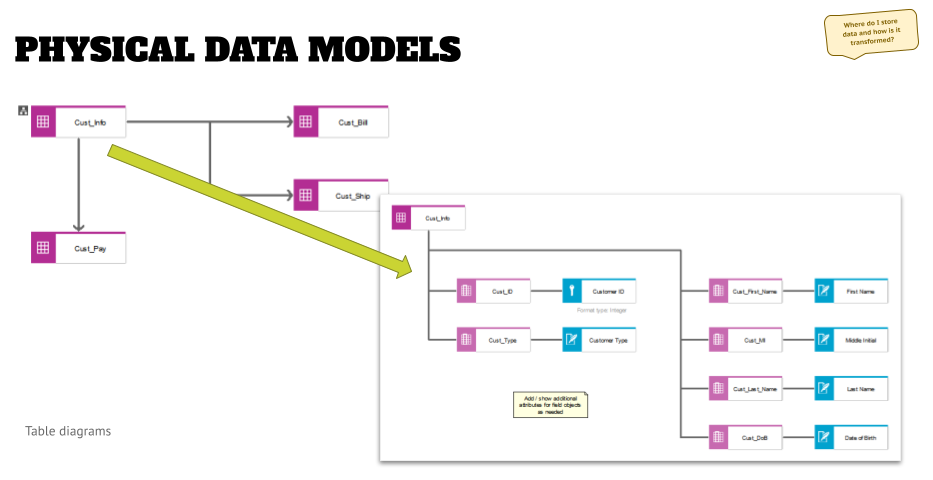
At this point we get into the physical data modeling, and the way to do this is to create two levels of physical data models, as shown below.
- If the application has an internal database, then you might want to create an assignment to a table diagram directly to the application system (type) object.
- If the application uses an external database system (as shown to the right in the graphic above), you might want to go to the instance modeling.
In either case, you need to define a consistent way of modeling as part of the meta model conversations, so that your artifacts are comparable, and you can create standardized analysis and dashboards.

The first level is a table diagram that shows the tables of the application and how they relate to each other. The example above is a very simplified version, and in projects I have seen much more complex diagrams. What you will see in those pretty quickly are tables that are very important and frequently used.
Once you have created the high-level table diagram, you can assign a level two table diagram to each table object.
In this you then can model the fields, and other objects, and then map them to the logical attributes. This does multiple things for you:
- You have a completeness check – all your logical attributes should find a home. If not, you either have a gap in your physical data design (missing fields or different relationships might be needed if a crucial logical attribute is stored in another table of your application, or even a different application that an interface needs to be built to), or you might identify an inefficiency in your database table design when you see unused fields.
- Another benefit is that you will see that some fields got reassigned over time, and their name does not reflect the content that shall be stored there – represented by the logical attribute. This might trigger an analysis if the data stored in various applications are really consistently handled.
- As part of the field attributes you can define the field format (e.g. “Text with x characters length”) and then compare this with the business requirement for formats that were identified when modeling the logical attributes.
- Once you have modeled these relationships for multiple apps/tables you can aggregate them and define your business requirement more clearly going forward, because you know that you have limitations in your applications, and the lowest denominator might define the maximum amount of available characters.
- You created a traceability that is valuable in regulatory obligations scenarios, such as data privacy regulations.
As with the applications above, you can create additional models when using table diagrams – you can create views of related data (“by topic”) to make it easier to follow for stakeholders or in workshops, as well as distinguish an “abstract” modeling (“by type”) or going into the specific field (“by instance”, for example, when you say “we typically have the fields specified like this -format-, but in the database on instance x we extended this format to 2 more characters for these and these reasons”).
Outlook
By modeling data down to the physical level you can trace the design, storage, and transformation of data in your architectures. By now you have answered the “what is my data?” and “where do I store/transform my data?” questions. In the last article of this series, we will have a look at the “where do I ask for the data” question, and will have a look at screen design and screen navigation modeling.
Roland Woldt is a well-rounded executive with 25+ years of Business Transformation consulting and software development/system implementation experience, in addition to leadership positions within the German Armed Forces (11 years).
He has worked as Team Lead, Engagement/Program Manager, and Enterprise/Solution Architect for many projects. Within these projects, he was responsible for the full project life cycle, from shaping a solution and selling it, to setting up a methodological approach through design, implementation, and testing, up to the rollout of solutions.
In addition to this, Roland has managed consulting offerings during their lifecycle from the definition, delivery to update, and had revenue responsibility for them.
Roland has had many roles: VP of Global Consulting at iGrafx, Head of Software AG’s Global Process Mining CoE, Director in KPMG’s Advisory (running the EA offering for the US firm), and other leadership positions at Software AG/IDS Scheer and Accenture. Before that, he served as an active-duty and reserve officer in the German Armed Forces.