How to model data (pt. 2) – more logical data models
In the previous article we spoke about the “why” and conceptual/logical data modeling. Today we will have a look at the distinction between canonical data model and information assets and the usage of logical data in application models and interfaces.
The last two articles of this series will talk about physical data modeling, and lastly the usage of data on screens and other models.
Canonical data model vs. information asset view
When defining your meta model (as shown for an architecture tool implementation here, where we looked at the process view as an example), you define levels and views. One of these views is the data view, and it typically includes three aspects:
- The conceptual/logical decomposition (the “canonical data model”) that we had a look at in the previous article
- The use of a subset of the canonical data model in the information asset view, and
- The physical data models describing the implementation of the data model in tables and fields
The biggest challenge that I see in projects when data shall be added to other models is the use of entities (the “things” that are defined from a business perspective) vs. the use of clusters (aka “entities in context”). Depending on your tool and/or chosen notation you only might be able to use cluster objects -for example when using BPMN models in ARIS (the ‘document’ symbols specified in the notation).
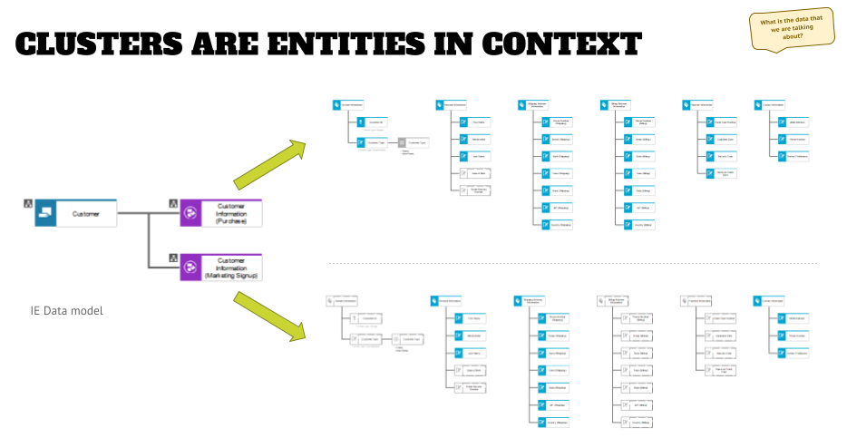
This is fine, but it also forces you to add another modeling as shown in the graphic below:

Here you see an entity “customer” that we’ve described in the previous article: personal information (name, day of birth, etc.), shipping and billing addresses (city, zip, street, etc.), or contact information (phone number, email, and so on).
What you also see is that this entity is mapped to two clusters – one that describes the customer information in the context of an order process, and one that shows the customer information in the context of a marketing signup process. In the examples to the right, I grayed out the attributes that are not used (in a real-life project I would have deleted the grayed out objects FWIW), and while both clusters share some attributes – like parts of the personal information, shipping (home) address, and contact information – there are specifics to an order that are not used elsewhere (billing address information for example).
This means that you can be very specific in the information definition / needs in a specific context, while on the other hand, you can build your canonical data model by layering the cluster models on top of each other, and aggregate the attributes in the assigned ERM diagram for the entity.
This will take out the big effort upfront “to get things right” in the first place, which might be a reason why so few projects do data modeling.
Applications and data (from a logical data model perspective)
Another way to use clusters, besides using them in processes, is to add them to application collaboration diagrams, which show the logical interfaces between two application systems (types) and which data will be sent to this interface.

Depending on the scope of your project you might do this in two ways:
- model it like alternative 1 and put the cluster between two applications, or
- connect the two applications and add an assignment to the connection.
Alternative two has a couple of advantages – first of all it de-clutters the application collaboration diagram, which helps reading large application landscapes significantly. Secondly, you can add additional information to the interface description, as indicated by adding the protocol object to the assigned model.
And lastly, you might run into the scenario that a large application with multiple modules might have interfaces with another large application with multiple models. Since you can create multiple assignments to the connection you can specify in the assigned model name which scenario you are describing when modeling the interfaces.
As with the above example, this also makes your model more resilient to future changes, because you will just have to change a lower-level model instead of changing the application landscape every time.
Use of logical data model objects when defining interfaces
As we’ve seen in a previous article, you can use logical data attributes also to map to each other for data interfaces that will detail the modeling from above. This will make it clear how attributes are mapped, even though there might be changes in names in the other application.
You can also create an assignment to a matrix model to the cluster objects shown above, so that you have this specification always available when looking at the cluster in other contexts.

I have seen matrices like this using physical field objects for the description of an interface – and it might be attractive to do this – but I would recommend to do this design using the logical attributes. The reason for that is that the technical implementation might change in the future (for example, when migrating an application to a new database system), and you have no insight into this, and the implementation project might not be aware of this artifact, which renders it useless.
The result of this will be that any analysis that you run on your database might now give you a “wrong” result, which is what you want to avoid.
This situation can be overcome when modeling physical and logical mappings as it will be shown in the next article. The matrix above will stay correct and relevant as the business requirements for the interface and changes to fields or table structures will be shown elsewhere.
Outlook
In the next article of this series, we will have a look at the physical data models. We will answer questions like “which tables are in this application” and “what are the fields in the tables and how are they defined”.
Roland Woldt is a well-rounded executive with 25+ years of Business Transformation consulting and software development/system implementation experience, in addition to leadership positions within the German Armed Forces (11 years).
He has worked as Team Lead, Engagement/Program Manager, and Enterprise/Solution Architect for many projects. Within these projects, he was responsible for the full project life cycle, from shaping a solution and selling it, to setting up a methodological approach through design, implementation, and testing, up to the rollout of solutions.
In addition to this, Roland has managed consulting offerings during their lifecycle from the definition, delivery to update, and had revenue responsibility for them.
Roland is the VP of Global Consulting at iGrafx, and has worked as the Head of Software AG’s Global Process Mining CoE, as Director in KPMG’s Advisory, and had other leadership positions at Software AG/IDS Scheer and Accenture. Before that, he served as an active-duty and reserve officer in the German Armed Forces.