How to model data (pt. 1) – why should I care and what are we talking about?
Data models are some of the things that I have seen the least often in projects over the last two decades. Why is that? Is it because it is too geeky, or not interesting enough compared to, say, a process model in BPMN?
This is the first article of a series that talks about data modeling: the why and conceptual/logical data modeling (this article), the distinction between canonical data model and information assets, the usage of logical data in application models and interfaces, the physical data modeling, and lastly the usage of data on screens and other models.
But let’s get started with the immediate question:
Why data modeling?
Data modeling has been long overlooked by business users because it was either seen as self-evident (what’s a “customer”?) and thereby seen as a waste of time, or was understood as the structure of the physical data fields of databases that stored the data.
But there is a problem with this – without specification of data structure and format, the implementer will make assumptions that might or might not catch what the business person wanted. This is not a good situation.
Data modeling is covering three big questions:
- What is the data that we talk about – conceptually (“what is a customer and what is it not?”) and logically (how should it be implemented without the details of the underlying application known?
- Where is the data stored and how is it transformed?
- Where do I ask for data and use it in the process?
The latter is very important today with the heightened awareness of data privacy and the laws that were released, especially in the European Union. By modeling the data as part of your solution design, all ambiguity is taken out of the development process, and the three questions above are easily answered.

Conceptual and logical data models – entities and relations
To design a conceptual/logical data model is crucial to get a business understanding of what we are talking about when it comes to the business problem at hand that shall be solved with the support of an application.
Therefore the definition of “things” is the first step. Remember the “customer” example? I was working on a project that after a couple of weeks came up with this definition: “A customer is an individual or organization that receives a product or service from us, and pays for it”.
This sound pretty straight forward, doesn’t it? The benefit of this definition was not so much to have this one term being defined, it was more what it did not define, or excluded. By this definition an employee who goes through an HR process, such as onboarding, is not a customer, even though the HR department thought so. A training participant in the training session might or might not be a customer (internal participants), so do you have to treat them differently / with different SLAs? And so on, and so on.
This means that the first step is to create a list of “things” and get a definition for them, which follows the “mutually exclusive” rule, meaning that if one thing is A, then it cannot be B. The “things” in data modeling speech are called “entities”.
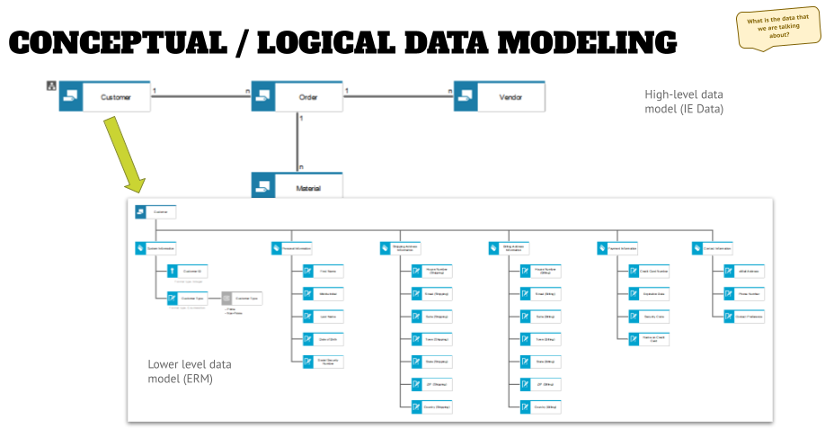
However, there can be a relationship between entities A and B. These relationships can be mapped out in an IE Data Model, and might look similar to the upper half of the graphic below.
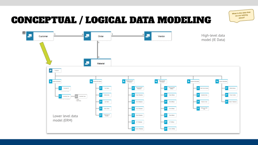
As you can see there are relationships between “Customer” and “Vendor” the “Order”. Without the order there would be no relationship in this scenario. However, there could be multiple indirect relationships between Customer and Vendor, for example, if an invoice has to be paid.
Once you have brought the entities into your architecture tool, and modeled the relationships, you can further specify the type of relationships between the entities. Is it a One-to-One relationship, which means a Customer can have only one Order, or is it One-to-Many relationship (which is more realistic because a Customer can have multiple Orders, even from the same Vendor). This information can be added to the connection, and either displayed as characters, as shown above, or with symbols on the connections. This is called “cardinality” in data modeling language.
Overall, it does not make a big difference in my opinion, if you use characters or symbols. If you model it like above (using characters) you might make things easier to understand for other business users, who might be too shy to ask what this weird chicken scratch on the connection means.
Also, keep in mind that you do not think about the specification of the entities at this point in time, and also do not try to categorize entities or limit yourself in identifying and defining these. The more mutually exclusive entities you can identify that are relevant for your solution, the better it is and the more complete your thinking and design will be.
Conceptual and logical data models – attributes
Once the main entities and their relations are defined from a business perspective, it is time to dive deeper and describe the next level of detail – what are the entities comprised of? For this you can create an assignment to an Entity Relationship Model, and start describing the entities from an attribute perspective (shown in the lower half of the graphic above).
- While doing this, keep in mind that we are still looking at the business perspective. Do not try to find the correct field names and add them here – most likely you will discover that the piece of information that you are describing, such as the name, is also used in other systems and the field name over there might be completely different.
- You can group the attributes in a logical fashion using attribute type groups. These are of no interest for developers, but will help you when reviewing your data models with business stakeholders.
- When defining the attributes you might want to define key, foreign key, and the standard descriptive attributes (note the different symbols in the light blue objects above). But do this from a business generic perspective (again), and do not focus on a specific implementation (yet).
- After that you can start defining the field formats – text, integer, date, and so on – and in the case of enumerations (pre-defined values), you can add the enumeration as an object (the gray symbol in the first “tree branch”), and add the values in an attribute that can be shown in the model if wanted.
Doing the latter two additions to an ERM diagram changes the data model from a conceptual to a logical model in the eyes of some methodologists. In reality it is just another enhancement of the model to another level of detail, which will help later in mapping exercises, as well as the implementation in bits and bytes.
Outlook
In the next article of this series, we will have a look at how the logical data models will fit into the meta model (the “data view”) and how logical data modeling will be used in application collaborations and for technical interface design.
Roland Woldt is a well-rounded executive with 25+ years of Business Transformation consulting and software development/system implementation experience, in addition to leadership positions within the German Armed Forces (11 years).
He has worked as Team Lead, Engagement/Program Manager, and Enterprise/Solution Architect for many projects. Within these projects, he was responsible for the full project life cycle, from shaping a solution and selling it, to setting up a methodological approach through design, implementation, and testing, up to the rollout of solutions.
In addition to this, Roland has managed consulting offerings during their lifecycle from the definition, delivery to update, and had revenue responsibility for them.
Roland is the VP of Global Consulting at iGrafx, and has worked as the Head of Software AG’s Global Process Mining CoE, as Director in KPMG’s Advisory, and had other leadership positions at Software AG/IDS Scheer and Accenture. Before that, he served as an active-duty and reserve officer in the German Armed Forces.